Table Of Content
At this point, I pretty much completed the entire ductwork design. I have the supply, return and fresh air ducts as well as diffusers and dampers. HVAC ducting is a vital component of any heating or air conditioning system, and The Duct Shop provides a variety of high-quality options. Choose from a selection of duct sizes and materials, including galvanized steel round snap-lock duct and flexible duct options, to meet your specific needs. The Duct Shop has the largest selection of quality sheet metal ducts, duct fittings, and airflow ducts forduct fitters andduct installers.
Calculate your airflow requirements
Now find the total duct losses for each duct and branch, that’s very easy to do simply multiply the duct length by the pressure drop per meter, in our example we found it to be 0.65pa/m. Now we need to label every section of ductwork as well as the fittings with a letter. Notice we are only designing a very simple system here so I’ve only included ducts and basic fittings, I’ve not included things such as grilles, inlets, flexible connections, fire dampers etc. The three branches within the main duct now receive equal air flow making a significant improvement to the design. This is because an additional branch now feeds the three smaller branches allowing some of the air to smoothly break away from the main flow and feed into these smaller branches.
The physics of air flow
To balance the system we need to add dampers to each of the branches to ensure equal pressure drop through all to achieve the design flow rates to each room. In the guides we find two tables the one you use depends on the direction of flow, we’re using the straight direction so we locate that one and then look up each ratio to find our loss coefficient. Here you can see both of the values we calculated fall between vales listed in the table so we need to perform a bilinear interpolation.
2 DYNAMIC LOSSES
A key factor in the location of mechanical equipment rooms is the source of outdoor air. Poorly diluted contaminants may cause odors, health impacts, and reduced indoor air quality. For rated performance, air must enter the fan uniformly over the inlet area in an axial direction without prerotation.
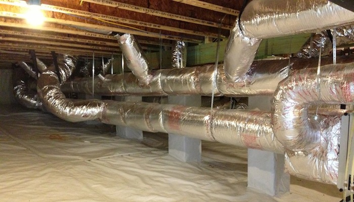
Using duct insulation as a design element - ACHR NEWS
Using duct insulation as a design element.
Posted: Thu, 06 Feb 2020 08:00:00 GMT [source]
Poor design or lack of system sealing can produce inadequate airflow rates at the terminals, leading to discomfort, loss of productivity, and even adverse health effects. Lack of sound attenuation may lead to objectionable noise levels. When sizing by the friction rate results in too high a velocity, we size by the velocity, which results in a larger duct. But larger ducts also result in less resistance, which means we may get too much air flow in that run.
In Equation (3), V (section average velocity) replaces v (streamline velocity) because experimentally determined loss coefficients allow for errors in calculatingv2/2 (velocity pressure) across streamlines. But just looking at those two sections of the duct calculator aren’t the end of the process. We also want to make sure the velocity of the air isn’t too high. In my example here, 400 cfm at 0.073 iwc/100′ corresponds to a velocity of about 725 feet per minute (fpm). To move 400 cfm on the return side in this duct system, we’d need to move to a larger duct. Let’s say we have a section of ductwork that needs to move 400 cfm.
We want to use the smoothest fittings possible for energy efficiency. For example use long radius bends rather than right angles as the sudden change in direction wastes a huge amount of energy. However, if you are not dealing with multiple rooms, you may choose to use free return that doesn’t require any return duct. Basically, you use the space above the ceiling as a plenum for return air.
Duct CFM Chart:
Refer to Chapter 19 of the 2020 ASHRAE Handbook—HVAC Systems and Equipment for leakage-related specifications for air-handling units. Roughness factors listed in Table 1, column 3, are recommended for use with Equation (19). For increased calculation accuracy, use an absolute roughness factor from column 2.
On the other hand, if flow starts to enter the right stack (Figure 3B), it creates a buoyancy effect in the left stack. In both cases, the produced thermal gravity effect is stable and depends on stack height and magnitude of heating. The starting direction of flow is important when using natural convection for ventilation.
To do this make sure you start at the main duct which is furthest away. Then we just add up the volume flow rates for all the branches downstream of this. For D that’s just the sum of L I and F and for duct A its then the sum of L, I, F and C. Collaborating with HVAC professionals is pivotal in achieving optimal ductwork design. They assess specific needs, calculate load requirements, and recommend design adjustments or upgrades tailored to the building’s unique characteristics. Professional expertise ensures that new installations or upgrades align with energy efficiency standards and deliver effective HVAC performance.
(The rule here is 400 cfm per ton.) That means the blower has to push about 81 pounds of air through the system each minute. We can calculate how much pressure drop each damper needs to provide simply by subtracting the loss of the run from the index run. We find it easily by adding up all the pressure losses from the start to the exit of each branch . Next we need to find the index run which is the run with the largest pressure drop. It’s usually the longest run but could also be the run with the most fittings.


No comments:
Post a Comment